Steam Boiler Piping Diagram PDF: A Comprehensive Guide
Today, March 23, 2026, understanding steam boiler systems requires focused education for contractors, especially regarding design and troubleshooting, differing significantly from hydronic systems.
Steam boiler systems represent a cornerstone of numerous industrial and commercial heating applications, demanding precise design and maintenance for optimal efficiency and safety. Understanding these systems necessitates a firm grasp of their fundamental principles, moving beyond conventional hydronic approaches. As Joe Coppola of the Hydronics Institute emphasizes, specialized knowledge is crucial for contractors.
Unlike hydronic systems, steam boilers operate with characteristics more akin to air conditioning units, requiring a distinct skillset for effective troubleshooting and design. A steam boiler piping diagram PDF serves as an essential tool, visually representing the complex network of pipes, valves, and components that constitute a functional system. These diagrams are not merely illustrations; they are critical blueprints for installation, repair, and ongoing system analysis.
Successfully navigating the intricacies of steam boiler systems relies heavily on accurate interpretation of these diagrams, ensuring correct component placement and proper operational flow.
Understanding the Core Components
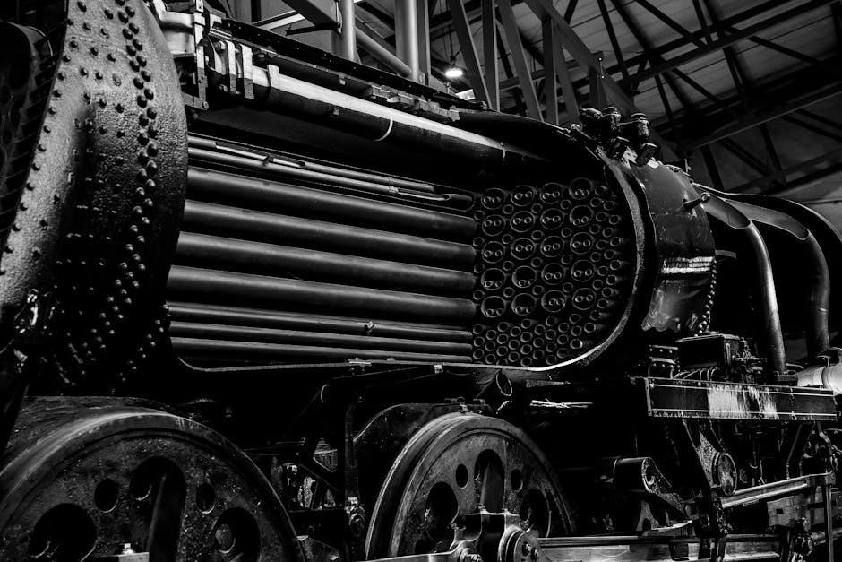
A steam boiler piping diagram PDF highlights the interconnectedness of vital components, each playing a crucial role in efficient steam generation and distribution. These diagrams visually deconstruct the system, revealing the boiler itself – where water is heated to produce steam – alongside essential elements like steam traps, safety valves, and pressure gauges.
Understanding these core components is paramount for effective system management. The diagram illustrates how the boiler connects to the main steam piping, delivering steam to various process loads. Equally important is the return piping, which channels condensate back to the boiler for reuse, maximizing efficiency. Joe Coppola’s emphasis on specialized training underscores the need to move beyond hydronic system knowledge.
Properly interpreting a piping diagram allows technicians to quickly identify component locations and understand their functions, facilitating swift troubleshooting and preventative maintenance.
Types of Steam Boiler Systems
Steam boiler piping diagram PDFs often categorize systems based on operating pressure, primarily distinguishing between low-pressure and high-pressure configurations. Joe Coppola stresses that steam systems operate differently than hydronic ones, a key consideration when interpreting diagrams.
Low-pressure steam systems, typically operating below 15 psi, are common in older buildings and smaller applications. Their diagrams showcase simpler piping layouts, focusing on gravity return lines and basic venting. Conversely, high-pressure steam systems, exceeding 15 psi, are found in industrial settings and power generation, demanding more complex diagrams.
These diagrams reveal robust piping networks, incorporating pumped condensate return systems and sophisticated control mechanisms. Understanding these distinctions is vital; a diagram for a low-pressure system won’t accurately represent a high-pressure setup. Correct interpretation, guided by the diagram, ensures safe and efficient operation.
Low-Pressure Steam Systems
Steam boiler piping diagram PDFs for low-pressure systems, generally below 15 psi, emphasize simplicity and gravity. Joe Coppola’s insights highlight that these systems resemble air conditioning units in operation, influencing diagram interpretation. Diagrams typically illustrate larger diameter pipes to accommodate steam volume and minimize pressure drop.
Key features include gravity return lines, directing condensate back to the boiler without pumps, clearly shown on the diagram. Venting is crucial, and diagrams detail vent placement to eliminate air pockets. These systems often utilize near-boiler piping, a compact arrangement depicted in the diagrams.
Understanding these diagrams requires recognizing the reliance on natural convection. A well-maintained low-pressure system, as illustrated in the PDF, prioritizes proper venting and condensate return for optimal efficiency and longevity. Diagrams serve as essential guides for troubleshooting and maintenance.
High-Pressure Steam Systems

Steam boiler piping diagram PDFs for high-pressure systems, exceeding 15 psi, demand meticulous design and detailed documentation. Unlike low-pressure counterparts, these systems necessitate pumped condensate return, prominently featured in diagrams. Joe Coppola’s emphasis on differing operational principles applies strongly here; these are not hydronic systems.
Diagrams illustrate complex piping arrangements, including superheated steam lines and sophisticated control valves. Precise pipe sizing is critical to manage velocity and prevent erosion, clearly indicated on the PDF. Safety considerations are paramount, with safety valve discharge piping meticulously mapped.
High-pressure systems often incorporate flash tanks and deaerators, components detailed in the diagrams. Understanding these PDFs requires a grasp of thermodynamics and steam properties. Proper interpretation ensures safe and efficient operation, vital for industrial applications and power generation.
Essential Piping Components in Steam Boilers
Steam boiler piping diagram PDFs meticulously detail crucial components. These include steam lines – conveying steam from the boiler to processes – and return lines, facilitating condensate flow back to the boiler. Understanding these is fundamental, as Joe Coppola stresses the unique nature of steam versus hydronic systems.
Essential elements highlighted in diagrams are valves (gate, globe, check), regulating steam flow and preventing backflow. Flanges and fittings connect pipe sections, while expansion joints accommodate thermal movement. Steam traps, vital for condensate removal, are clearly shown.
Diagrams also illustrate pressure gauges, safety valves, and vents, ensuring safe operation. Pipe insulation, though not always visually represented, is critical for efficiency. Accurate interpretation of these components within the PDF is paramount for effective system maintenance and troubleshooting;
Steam Boiler Piping Diagram Basics
Steam boiler piping diagram PDFs fundamentally illustrate steam’s journey from generation to utilization and return. These diagrams aren’t simply plumbing schematics; they represent energy transfer, demanding a different approach than hydronic systems, as Joe Coppola emphasizes.
Basic diagrams showcase the boiler itself, connected to main steam piping distributing steam to various loads. Return piping then collects condensate, returning it to the boiler for reuse. Key symbols represent valves, traps, and gauges, each with standardized representations.
Understanding flow direction is crucial – steam out, condensate back. Color-coding often distinguishes steam and condensate lines. These diagrams are essential for contractors needing to correctly design, troubleshoot, and maintain these unique systems, moving beyond traditional hydronic knowledge.
Main Steam Piping

Main steam piping, depicted clearly in a steam boiler piping diagram PDF, carries high-temperature, high-pressure steam from the boiler to the points of use throughout a facility. Its design is critical, demanding careful consideration of pipe diameter to prevent excessive pressure drop and ensure adequate steam supply;
Diagrams illustrate the piping’s route, often including risers and branches, with strategically placed valves for isolation and control. Slope is vital; a slight grade ensures condensate drains back towards the boiler, preventing water hammer and corrosion. Insulation is paramount, minimizing heat loss and maintaining steam quality.
Understanding the layout, as shown in the PDF, allows technicians to trace the steam’s path, identify potential bottlenecks, and perform effective maintenance. Proper design, diverging from hydronic approaches, is key to efficient operation, as Joe Coppola highlights.

Return Piping
Return piping, a crucial element detailed in a steam boiler piping diagram PDF, facilitates the flow of condensate – water formed when steam releases its heat – back to the boiler. Unlike supply lines handling high-energy steam, return lines operate under lower pressure and temperature, but are equally vital for system efficiency.
Diagrams showcase the return piping’s network, often mirroring the main steam lines, with a gentle slope towards the boiler to aid gravity-driven condensate return. Proper sizing prevents condensate backup, which can cause water hammer and corrosion.
Effective return systems, as emphasized by industry experts like Joe Coppola, are fundamentally different from hydronic systems. A well-designed return, clearly illustrated in the PDF, minimizes water loss and maximizes boiler efficiency, contributing to significant energy savings and operational reliability.
Key Elements of a Steam Boiler Piping Diagram PDF
A comprehensive steam boiler piping diagram PDF transcends a simple visual representation; it’s a detailed blueprint for system understanding and maintenance. Essential elements include clearly labeled main steam lines, return piping networks, and the strategic placement of steam traps.
Safety valves and their corresponding piping connections are prominently featured, highlighting critical pressure relief mechanisms. Pressure gauges and control systems are also depicted, illustrating monitoring and regulation points.
Furthermore, the diagram specifies pipe sizes, materials, and insulation details. As Joe Coppola of the Hydronics Institute stresses, correct design is paramount. The PDF should also include component specifications and, ideally, a bill of materials, enabling accurate troubleshooting and replacement of parts, ensuring optimal system performance.
Safety Valves and Piping Connections
Safety valves are paramount in steam boiler systems, acting as crucial pressure relief devices. A detailed steam boiler piping diagram PDF must clearly illustrate their location and connection to the boiler shell. These valves prevent catastrophic failure by automatically releasing excess pressure, safeguarding equipment and personnel.
The piping connected to safety valves requires specific consideration; it must be sized correctly to handle the full discharge capacity of the valve without creating backpressure. Discharge piping should terminate safely, directing steam away from personnel and equipment.
Diagrams should also depict any test valves or isolation points for maintenance. As emphasized by industry experts, proper valve selection and piping configuration are vital for reliable operation, aligning with Joe Coppola’s focus on correct system design.
Steam Traps: Function and Placement
Steam traps are essential components in any steam boiler system, automatically discharging condensate, air, and non-condensable gases while preventing live steam loss. A comprehensive steam boiler piping diagram PDF must accurately depict their strategic placement throughout the piping network.
Proper trap selection and installation are critical for efficient operation and preventing water hammer. Diagrams should illustrate different trap types – float, thermostatic, and thermodynamic – and their appropriate applications. Locations include steam mains, drip legs, and at the ends of steam lines.

Understanding trap function, as part of broader hydronic system knowledge highlighted by Joe Coppola, is key to effective troubleshooting. The diagram should clearly show the flow path through each trap, aiding in identifying and resolving issues like airlocks or waterlogging.
Condensate Return Systems
Condensate return systems are vital for boiler efficiency, recovering heated water for reuse and minimizing makeup water requirements. A detailed steam boiler piping diagram PDF must clearly illustrate these systems, showcasing their configuration and components.
Two primary types exist: gravity return systems, relying on elevation differences, and pumped return systems, utilizing pumps for condensate transport. The diagram should differentiate between these, indicating pipe slopes for gravity systems and pump locations for pumped systems.
Effective condensate return, a crucial aspect of hydronic system design as emphasized by Joe Coppola, requires careful consideration. The diagram should show condensate receivers, vents, and any necessary filtration. Proper depiction aids in troubleshooting and optimizing system performance, preventing issues like corrosion and scaling.
Gravity Return Systems

Gravity return systems, a traditional approach to condensate management, depend on the natural slope of piping to return condensate to the boiler. A comprehensive steam boiler piping diagram PDF must meticulously detail these slopes, typically a minimum of ¼ inch per foot, ensuring effective drainage.
These systems are simpler and require less maintenance than pumped alternatives, but their application is limited by building layout and elevation constraints. The diagram should clearly illustrate the elevation differences driving the return flow, highlighting condensate receivers strategically placed along the piping run.
Understanding these systems, as emphasized in hydronic system education, is crucial for contractors. The PDF should show vent points to prevent airlocks, hindering gravity flow. Proper design, reflected in the diagram, minimizes energy loss and maximizes boiler efficiency.
Pumped Return Systems
Pumped return systems offer greater flexibility in condensate return, overcoming the limitations of gravity-based designs. A detailed steam boiler piping diagram PDF is essential, showcasing the pump’s location, capacity, and control mechanisms. These systems are particularly valuable when gravity return isn’t feasible due to building layout or elevation differences.
The diagram must illustrate the pump’s suction and discharge piping, including strainers to protect the pump from debris. Proper sizing of the pump is critical, ensuring efficient condensate removal without excessive energy consumption. Control strategies, like level sensors in the condensate receiver, should be clearly depicted.
Contractor education, as advocated by the Hydronics Institute, stresses the importance of understanding pump curves and system head loss. The PDF should include details on piping materials and insulation to minimize heat loss, maximizing system efficiency and reliability.
Venting and Air Removal
Effective venting and air removal are crucial for optimal steam boiler operation, and a comprehensive steam boiler piping diagram PDF must clearly illustrate these systems. Air pockets impede heat transfer and can cause damaging water hammer. Venting removes non-condensable gases, while air removal tackles accumulated air within the system.
The diagram should detail vent locations – at high points in the steam and condensate lines – and the type of vents used (automatic, thermostatic, or manual). It must also show air separators, strategically placed to capture and remove entrained air. Proper sizing of vents is paramount, preventing both air binding and steam loss.
Understanding these systems requires contractor education, as highlighted by the Hydronics Institute. The PDF should include details on vent maintenance and troubleshooting, ensuring long-term system efficiency and preventing operational issues.
Pressure Gauges and Controls
A detailed steam boiler piping diagram PDF must prominently feature pressure gauges and control systems, vital for safe and efficient operation. These gauges monitor steam pressure within the boiler and throughout the distribution network, providing critical operational data. Control systems, including pressure regulating valves and low-water cutoffs, are essential safety features.
The diagram should clearly indicate gauge locations – on the boiler shell, steam lines, and potentially at the end of steam mains – alongside their specified ranges. Control system components, like pressure switches and sensors, need precise placement noted.
Contractor education, as emphasized by the Hydronics Institute, is key to correctly interpreting these readings and maintaining control systems. The PDF should include information on calibration, testing, and troubleshooting these crucial components, ensuring reliable performance.
Materials Used in Steam Boiler Piping
A comprehensive steam boiler piping diagram PDF must detail the materials used in construction, as material selection impacts longevity and safety. Traditionally, carbon steel piping was standard, but modern systems increasingly incorporate alloy steels for enhanced corrosion resistance, particularly in condensate return lines.
The diagram should clearly specify pipe schedules (e.g., Schedule 40, Schedule 80) and fitting types. Flanges, valves, and couplings also require material designation. Understanding these specifications is crucial for contractors, aligning with the Hydronics Institute’s focus on proper system design.
The PDF should note considerations for thermal expansion and contraction, influencing material choices and expansion joint placement. Proper material selection, alongside accurate diagram interpretation, ensures a robust and reliable steam system.
Common Piping Configurations
A detailed steam boiler piping diagram PDF will illustrate prevalent configurations, moving beyond basic schematics; One-pipe and two-pipe systems are fundamental, with the diagram clearly showing steam flow direction and condensate return paths. Variations exist, including reverse-return systems offering improved heat distribution.
The PDF should depict typical layouts for low-pressure steam systems, differing significantly from hydronic designs as Joe Coppola emphasizes. Branching methods, drip leg placement, and the integration of steam traps are vital components to showcase.
Understanding these configurations is essential for troubleshooting, aligning with the Hydronics Institute’s training goals. Accurate diagrams enable contractors to quickly identify potential issues and implement effective solutions, ensuring optimal system performance.
Troubleshooting Piping Issues
A comprehensive steam boiler piping diagram PDF is invaluable for diagnosing common problems. Water hammer, caused by rapid steam condensation, is frequently linked to improper piping or absent drip legs – the diagram aids in identifying these areas.
Air locks, hindering steam flow, can be pinpointed by tracing the piping layout and locating potential air accumulation points. Leaks, often at joints or valves, are readily visible on a detailed diagram, facilitating swift repair.
Joe Coppola’s emphasis on correct system design directly impacts troubleshooting; a poorly designed system, revealed by the diagram, will inevitably present more challenges. The PDF should support contractors in applying hydronic system knowledge cautiously, recognizing steam’s unique operational characteristics.
Resources for Steam Boiler Piping Diagrams (PDFs)
Accessing reliable steam boiler piping diagram PDFs is crucial for both design and maintenance. While a single definitive online repository isn’t explicitly mentioned, professional organizations like the Hydronics Institute, where Joe Coppola contributes, likely offer resources or can direct members to relevant materials.
Boiler manufacturers frequently provide detailed diagrams specific to their equipment, often available through their websites or upon request. Industry-specific publications and training courses may also include downloadable PDFs as part of their curriculum.
Searching online using precise keywords – “steam boiler piping diagram PDF,” “low-pressure steam system diagram,” or manufacturer-specific searches – can yield results. Always verify the source’s credibility to ensure accuracy and compliance with current standards.
Regulatory Compliance and Standards

Ensuring steam boiler piping diagrams adhere to regulatory standards is paramount for safety and operational efficiency. While the provided text doesn’t detail specific regulations, proper design and troubleshooting, as emphasized by the Hydronics Institute’s Joe Coppola, inherently involve compliance.
Local and national codes govern boiler installations, dictating requirements for materials, safety devices, and piping configurations. Diagrams must accurately reflect these stipulations to pass inspections and avoid potential hazards.
Adherence to standards set by organizations like the ASME (American Society of Mechanical Engineers) is often mandatory. Diagrams should clearly demonstrate compliance with pressure vessel codes and safety valve specifications. Thorough documentation and accurate representation are vital for regulatory approval.
Future Trends in Steam Boiler Technology
The evolution of steam boiler technology, while not directly addressed in the provided text, will inevitably impact piping diagrams and their associated PDFs. A growing emphasis on efficiency and integration with modern control systems is anticipated.
Future diagrams may increasingly incorporate digital twin technology, offering interactive 3D models linked to real-time operational data. This allows for remote monitoring, predictive maintenance, and optimized performance.
Furthermore, advancements in materials science could lead to piping systems with enhanced corrosion resistance and thermal performance, reflected in updated diagram specifications. The need for skilled contractors, as highlighted by the Hydronics Institute, will remain crucial for implementing these innovations and interpreting complex diagrams.